Offers you the possibility to design circuits by applying digital logic concepts and test the results by simulating the effects.. #Circuit design #Interactive circuit #Digital logic #Circuit #Design #Simulate
LogicWorks provides simple tools and an organized environment for quickly creating visual representations for circuits. The app is great as an educational tool since it allows you to practice digital logic concepts.
LogicWorks offers you the possibility to simulate the effects of a certain circuit: this way you can test its viability without actually taking the time to make the physical connections between different instruments.
To get started, you must draw the circuit in the schematic editor: it comes with interactive connection tracing (it will automatically detect signal line connections), bussing and multi level undo and redo capabilities. Moreover, you can make your own text annotations.
The LogicWorks editor enables you to copy/cut/paste circuit elements, can reroute lines when you move symbols, allows you to set up your own device symbols and define their internal circuit and much more.
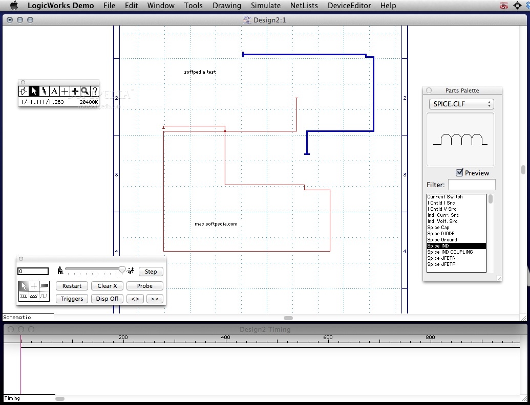
Since the editor is connected to a digital simulator, both the device parameters changes and the signal connections changes are expressed in timing waveforms that will be visible in the Design Timing area.
The LogicWorks Simulator can show multiple signals at the same time, enables you to create a single timing value for a group of signals and comes with built-in support for ROMs, PLAs and RAMs.
To learn more about what you can achieve using LogicWorks, you can consult the extensive user manual that in included in the Help area.
Last and not least, the LogicWorks export files are compatible with the more complex and powerful DesignWorks application: you can draw your test circuit in LogicWorks and then you can use DesignWorks for a more in depth analysis.
LogicWorks can be both an educational tool, that helps you practice your capability to use digital logic concepts, and a very efficient test tool that can determine the viability of a circuit design.
What's new in LogicWorks 4.7.9:
- Fixed problem with tool palette that occurred under OS X 10.12.5.
LogicWorks 4.7.9
add to watchlist add to download basket send us an update REPORT- runs on:
- Mac OS X 10.6.6 or later (Intel only)
- file size:
- 4.7 MB
- filename:
- LogicWorks_Demo.dmg.zip
- main category:
- Math/Scientific
- developer:
- visit homepage
7-Zip

4k Video Downloader

IrfanView

paint.net

Windows Sandbox Launcher

Bitdefender Antivirus Free

Microsoft Teams

Zoom Client

calibre

ShareX

- Zoom Client
- calibre
- ShareX
- 7-Zip
- 4k Video Downloader
- IrfanView
- paint.net
- Windows Sandbox Launcher
- Bitdefender Antivirus Free
- Microsoft Teams